This document shows you how to use this applet in a step-by-step manner. You should have the applet open; toggle back and forth between
the ShowMe file and the applet as you work through these instructions.
| Free Body Diagrams are
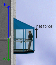
automatically created and appear as blue and green force vectors drawn
on the left side of the elevator. The blue vector represents the normal
force of the elevator pushing up on the occupant (N), while the green
vector represents the force of gravity or weight pulling down on the
occupant (W). A "net force" indicator on the right of the
elevator gives you a visual representation of the sum of these two forces.
- Note that as you adjust the mass of the occupant, both N and W change
in response to this and, as long as the elevator is not accelerating,
will have identical lengths. Try changing the mass to observe this.
|
 |
- The free body diagram can easily be turned into an equation:
 . Since the net force is
zero in this initial setup, you can see that the normal force of the
elevator on the occupant is precisely equal to the weight of the occupant.
If the person is standing on a scale, then the scale would be providing
the normal force and this in turn would imply that the scale reading
would equal the weight of the person. . Since the net force is
zero in this initial setup, you can see that the normal force of the
elevator on the occupant is precisely equal to the weight of the occupant.
If the person is standing on a scale, then the scale would be providing
the normal force and this in turn would imply that the scale reading
would equal the weight of the person.
- For example, set the mass of the occupant to equal 80 kg. Since
the scale reading should equal the weight of the person, you should
see that
 . You can
confirm this by checking the scale reading information that is given
in the output window at the upper left area of the applet ( . You can
confirm this by checking the scale reading information that is given
in the output window at the upper left area of the applet ( ). ).
|
- To continue the example, adjust the acceleration to 4 m/s2
and click "Up". The occupant (and elevator) will begin to
accelerate upward. Since a force is required for an acceleration, you
should expect to see this reflected in the free body diagram. Your diagram
should look like the one shown below. This also implies the following
equation:
 . Since we
know that a = 4 m/s2, we can solve this equation
for N . This gives us . Since we
know that a = 4 m/s2, we can solve this equation
for N . This gives us  . .
If we insert the correct values, we find that N has now grown to
(80 kg) (4 m/s2)+784.8 N = 1104.8 N.
This is reflected in the slightly longer arrow shown for N in the
FBD.
|
 |
- Notice that after a few seconds of motion, the elevator
begins to coast. At this point, the net force must once again drop to
zero and we also see that N = W and that the scale reading is once
more equal to the weight.
|
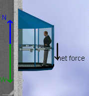
- Finally, the elevator begins to decelerate. Now the net
force on the occupant is in the opposite direction and the free body
diagram implies the following equation:
 . .
If we solve for N we find
 , and N = 464.8 N. This means
that the scale reading has dropped, and the occupant's apparent weight
is now lower. , and N = 464.8 N. This means
that the scale reading has dropped, and the occupant's apparent weight
is now lower.
|
 |
- It is very easy to display position, velocity, and acceleration time
graphs for the elevator. For example, set the acceleration of the elevator
at 3 m/s2 and click "Up". The elevator will
accelerate upward, coast, and then decelerate to a complete stop. Click
"View Graph", and select time for the x-axis and displacement
for the y-axis options. The position-time graph for this motion is shown
below.
- You now may use the various graphing tools to examine the graph. For
example, use the slope tool to measure the slope of the position-time
graph for any time during the motion of the elevator. When you press
this button, a blue slope arrow appears on the curve. You can move this
arrow along the curve by dragging it with the mouse. The slope of a
position-time graph tells you its velocity, so by using this tool you
can determine the velocity of the elevator. As an example, find the
slope at t = 32 s. Either drag the blue slope arrow along the curve
until the time (x-axis value) equals 32 s, or double-click on the
slope button and enter 32 s in the text box that opens. The slope
appears in the "output" window of the graph and indicates
a value of 78.0 m/s. You can confirm this by either re-running
the applet and noting the velocity when t = 32 s or by creating
a velocity-time graph.
|
 |
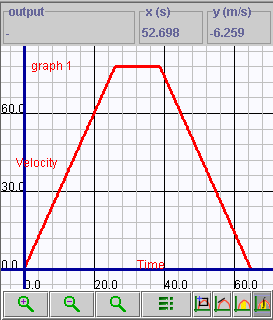
- Make a velocity-time graph for this motion, similar to the
sample graph shown below. Again, you can use graphing tools to examine
this graph. It also is easy to see that the elevator's motion consists
of 3 phases: speeding up, coasting, and decelerating. By using the slope
tool, you could measure the accelerations in the 3 phases and compare
them with the values found by plotting an acceleration-time graph.
|
 |
- A very useful feature of the graphing tool is the ability for the
user to define his or her own functions. For example, we could graph
the changing kinetic energy of the occupant in the elevator as the
elevator moves through its complete motion.
To illustrate this, set the mass of the occupant to 80 kg and
the acceleration to 4 m/s2. Since kinetic energy is
given by the expression  ,
we can create this by clicking the data collection button and choosing
the select data option. ,
we can create this by clicking the data collection button and choosing
the select data option.
|
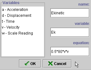
- A new dialogue box opens that lists the variables currently
available to you. Choose "Add" and then proceed to fill out
the template that opens (see the next diagram).
|
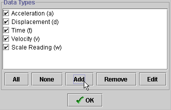 |
- A new variable (Ek) has been defined by the equation
0.5*80*v*v. (Alternately, you could have written this as 40*v*v). When
you click "OK", this variable will now become active and can
be plotted.
|
 |
- The graph of kinetic energy vs. time is shown on the right.
To create this graph, choose the new variable Ek for the y-axis and
time for the x-axis.
- You can enter other functions and their graphs by following the
steps described above.
|

 . Since the net force is
zero in this initial setup, you can see that the normal force of the
elevator on the occupant is precisely equal to the weight of the occupant.
If the person is standing on a scale, then the scale would be providing
the normal force and this in turn would imply that the scale reading
would equal the weight of the person.
  . You can
confirm this by checking the scale reading information that is given
in the output window at the upper left area of the applet (
 ).
). . Since we
know that a = 4 m/s2, we can solve this equation
for N . This gives us
  .
.
 .
. , and N = 464.8 N. This means
that the scale reading has dropped, and the occupant's apparent weight
is now lower.


 ,
we can create this by clicking the data collection button and choosing
the select data option.

