ShowMe - Light Reflection
Light Reflection simulates the Law of Reflection and explores the relationship
between the angle of incidence and the angle of reflection.
This document shows you how to use this applet in a step-by-step manner. You should have the applet open; toggle back and forth between
the ShowMe file and the applet as you work through these instructions.
Contents
- One Mirror Reflection and the Law of Reflection
- Two Mirror Reflection
1. One Mirror Reflection and the Law of Reflection
- Select the one mirror radio button. A blue, plane mirror will be drawn
and the red laser pointer will automatically direct a beam to the centre
of the mirror, as shown in the figure below.
- The mirror can be moved to any location in the drawing window by
holding down the left mouse control button and dragging it to the
new location.
- The mirror can be rotated to any angle by adjusting the mirror 1
slider. Note that in the single mirror option, the slider for mirror
2 is inactive.
|
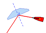 |
- A blue, dashed line is drawn at the point where the laser
beam reflects from the mirror. This is the surface normal and
the reflection is numbered (with a 1 in this case).
|
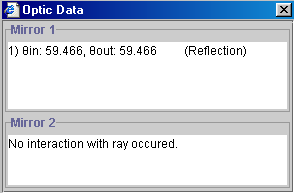
- The Law of Reflection is easy to demonstrate with this
applet. Click the Data control button. This will open the Optic Data
dialog box as shown below. θin
represents the angle of the incident ray with respect to the normal
line, and θout represents the
angle of the reflected ray. It is easy to verify that these angles
are equal.
|
 |
2. Two Mirror Reflection
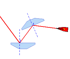
- Select the two mirrors radio button. Blue, plane mirrors will be drawn
and the red laser pointer will automatically direct a beam to the centre
of the first mirror, as shown in the figure below.
- Either mirror can be moved to any location in the applet display
panel by holding down the left mouse control button and dragging it
to the new location.
- Each mirror can be rotated to any angle by adjusting the appropriate
mirror slider.
|
 |
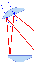
- If the mirrors are oriented so that multiple reflections
occur, then each point of reflection will be numbered, as shown in the
figure below. The angle of incidence and angle of reflection will be
given for each mirror in the Optic Data dialog box when the Data control
button is clicked.
|
 |
Physics 20-30 v1.0
©2004 Alberta Learning (www.learnalberta.ca)
Last Updated: June 16, 2004