Students should understand the vector properties of magnitude and direction and be familiar with adding vectors graphically by the Tip-to-Tail method. They should also have a working knowledge of basic trigonometry.
Students will learn to calculate the magnitude and direction of the sum of two vectors (resultant) given the magnitudes and directions of the two vectors to be added. They will learn to use the Law of Cosines and the Law of Sines for this purpose. They will also learn how to calculate the sum of two vectors using components.
Students should understand the applet functions that are described in Help and ShowMe. The applet should be open. The step-by-step instructions on this page are to be done in the applet. You may need to toggle back and forth between instructions and applet if your screen space is limited.
Appendix
Imagine you are re-entering the atmosphere in the space shuttle. In order to land the shuttle safely, the pilot must make an exact approach to the runway. In order to do this, the pilot needs to know the shuttle's exact velocity relative to the ground at all times. On re-entry, the shuttle is traveling at 130 m/s at 140° relative to the air when it enters the jet stream (high altitude, global air circulation) which moves at 100 m/s at 60° relative to the ground. What is the shuttle's velocity relative to the ground after it enters the jet stream? You may be tempted to say 100 m/s + 130 m/s = 230 m/s. This however, would be incorrect. Velocity is a vector quantity and as such the two velocities must be added as vectors. The applet will be used to illustrate how two vectors are correctly added.
The applet will be used to determine the shuttle's velocity relative to the ground at re-entry.
Figure 1 According to the applet, the shuttle's velocity relative to the ground at re-entry would be 177.24 m/s at 106.25° in the polar positive mode. |

Circle the correct answer below. The graphical construction of the resultant in Figure 1 illustrates the

The resultant from Exercise 1 may be displayed in three modes. Click the mode
control button (![]() )
for the resultant,
)
for the resultant,  , three times and cycle
to the "Cartesian" mode (
, three times and cycle
to the "Cartesian" mode ( ).
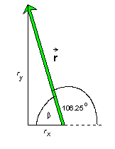
In this mode, the resultant's x- and y- components (rx,ry)
are displayed, as shown in Figure 2.
).
In this mode, the resultant's x- and y- components (rx,ry)
are displayed, as shown in Figure 2.
| Button | Mode | Example |
| Magnitude and polar positive direction (r,θ) |  |
|
| Magnitude and navigational direction (r,θ E of N ) |  |
|
|
Cartesian Components (rx,ry) |  |
Using the mode control button, describe the shuttle's velocity relative to the ground using all three modes.
)
is (________ , ________ deg))
is (________ , ________ E of N )) are (________
, ________)How is the resultant being calculated? It can be found using two different methods.
To calculate the magnitude and direction of the resultant as displayed in Figure 1, we need a diagram showing all relevant quantities as in Figure 2 below.
Figure 2 We want to calculate the magnitude r of the resultant The Law of Cosines is used to calculate the magnitude (r) and the Law of Sines is used to calculate the angle (α). For a description of these laws, see the appendix. |
| According to Figure 2, the Law of Cosines can be used to calculate
the magnitude (r) of the resultant vector:
(Note: the angle opposite to vector
|
|
The Law of Sines can then be used to calculate the direction (θ) of the resultant vector. To apply the Law of Sines, pair the angle (α) with the opposite side of magnitude (v2) and the 100° angle with the opposite side of magnitude (r). Therefore, the resultant vector has a magnitude of 177.24 at an angle of 106.25° in the polar (positive) direction:
|

Using the Law of Cosine and Sines, calculate the resultant (sum) of the following two vectors. Add the vectors on the applet in order to view the correct Tip-to-Tail vector diagram and verify the resultant.
 1 = 150, 50° polar (positive)
2 = 200, 150° polar (positive)
Tip-to-Tail vector diagram: |
Resultant magnitude (r): |
Resultant direction (θ): (Use the Law of Sines and polar (positive) specification.) |

Using the Law of Cosine and Sines, calculate the resultant (sum) of the following two vectors. Add the vectors on the applet in order to view the correct Tip-to-Tail vector diagram and verify the resultant.
1 = 100, 150° polar (positive)
2 = 75, 250° polar (positive)
Tip-to-Tail vector diagram: |
Resultant magnitude (r): |
Resultant direction (θ): (Use the Law of Sines and polar (positive) specification.) |
| We will now calculate the sum of the same two
vectors 1 and 2
as in the preceding section, but this time using components.
For the following calculations, you will need to know the (scalar) components of a vector. For an overview of vector Components, see the appendix. It is particularly easy if the vectors are already given in terms of their (x, y) components, (vx, vy)1 and (vx, vy)2. However, we will assume the vectors are given in terms of magnitude and direction [(v1, θ1) and (v2, θ2)]. Angles are measured in the polar (positive) specification (or navigation N of E). See Figure 3.
Figure 3 The magnitude and direction of v1 = 100, θ1 = 60° v2 = 130, θ2 = 140° |
|||||||||||
|
To add the two vectors is to add the respective components. If
the components of the resultant
|
|||||||||||
You could specify the resultant in terms of the components and stop the calculation at this point. However, if the magnitude and direction angle of the resultant are required, these can be calculated from the components as follows.
Again, it is very helpful to make a diagram to illustrate the angles and other relevant quantities involved. See Figure 4 below.
Figure 4 |
The triangle formed by the vector
|
| From Figure 4 we can see that the direction can be
calculated using the definition of the tangent of an angle.
This implies for the direction angle of Therefore, the resultant vector is 177.24 at 106.25° in the polar (positive) direction. You can verify these values on the applet by selecting the magnitude and polar positive direction for the resultant:
|
In summary, if two vectors 1 and 2
are given in terms of magnitude and direction, a resultant can be calculated
by doing the following:
This may be a bit more work than to calculate the resultant using the Law of
Cosines and the Law of Sines as was done in the preceding section. However,
if the two vectors 1 and 2
are already given in component form and if one wants the resultant in component
form as well, as will often be the case, the calculation is simpler.

Using the component method, calculate the resultant (sum) of the following two vectors. Show all required calculations and diagrams below and identify the direction using the polar (positive) specification. Add the vectors on the applet in order to verify the resultant magnitude and direction.
1 = 175, 70° polar (positive)
2 = 200, 200° polar (positive)
|
a. Vector diagram and calculation of the components for |
b. Vector diagram and calculation of the components for |
c. Addition of the components and drawing of the resultant vector.
d. Calculation of the resultant magnitude using the Pythagorean theorem.
e. Calculation of the resultant direction using the tangent function. Express the direction in terms of the polar (positive) specification.

Using the component method, calculate the resultant (sum) of the following two vectors. Show all required calculations and diagrams, and identify the direction using the polar (positive) specification. Add the vectors on the applet in order to verify the resultant magnitude and direction.
1 = 185, 45° polar (positive)
2 = 95, 320° polar (positive)
| a. Vector diagram and calculation of the components
for 1. |
b. Vector diagram and calculation of the components
for 2. |
c. Addition of the components and drawing of the resultant vector.
d. Calculation of the resultant magnitude using the Pythagorean theorem.
e. Calculation of the resultant direction using the tangent function. Express the direction in terms of the polar (positive) specification.

Using the component method, calculate the resultant (sum) of the following two vectors. Show all required calculations and diagrams below and identify the direction using the polar (positive) specification. Add the vectors on the applet in order to verify the resultant magnitude and direction.
1 = (+135, -120) - components 2 = (-200, -45) - components
a. Addition of the components and drawing of the resultant vector:
b. Calculation of the resultant magnitude using the Pythagorean theorem:
c. Calculation of the resultant direction using the tangent function: (express the direction in terms of the Polar (positive) specification)
Appendix
| The Law of Cosines is a general equation relating three sides
and one angle in a triangle. There are no restrictions on the triangle's
shape. Three elements determine a triangle. If any three of the four elements
in the law-of-cosines equation are given, the equation allows you to calculate
the fourth one.
Figure A1 illustrates a general triangle. The three sides are labeled a, b, c, and the three angles are labeled α, β, γ.
Figure A1 |
There are three law-of-cosines equations, depending on which angle is included:
c2 = a2 + b2 - 2ab cos γ (A1)
a2 = b2 + c2 - 2bc cos α (A2)
b2 = c2 + a2 - 2ca cos β (A3)
Note that the Pythagorean theorem is a special case of these equations if one of the angles is equal to 90°. For example, if γ = 90°, then cos γ = 0 and Equation (A1) reduces to the Pythagorean theorem:
c2 = a2 + b2 (A4)
Also note the minus sign in front of the cosine term in these equations. This has the following effect. Let's consider Equation (1). If γ < 90° , the cosine is positive. With the minus sign in front of the cosine term, Equation (A1) gives a value for c that is less than the value given by the Pythagorean theorem (4). If γ > 90°, the cosine is negative. Combined with the minus sign in front of the cosine term, the term now makes a positive contribution to the right-hand side of Equation (1) that yields a value of c that is greater than the one given by the Pythagorean theorem.
| The Law of Sines is a set of equations true for any triangle.
It states that the ratio "sine of an angle divided by the length of
the opposite side" is the same for any pair of angle and opposite side.
Figure A2 illustrates a general triangle. The three sides are labeled a, b, c, and the three angles are labeled α, β, γ.
Figure A2 |
The law-of-sines equations are:
 (A5)
(A5)
A triangle is determined by three of its elements. Given two sides and an angle opposite to one of the sides, the Law of Sines lets you to determine the angle opposite to the other side.
Vectors can be described in terms of their scalar components. A vector
in two dimensions has two scalar components, one along the x-axis
and one along the y-axis. For a vector
Figure A3 The scalar components of a vector are the vector's projections onto the x and y axes. In Figure A3, they are shown in green and yellow, respectively. They are called scalar components because they are numbers. The scalar components are equal to the x and y coordinates of the tip of the vector if the tail end of the vector is at the origin of the coordinate system, as it is here. |
The vector in Figure A3 has a magnitude of 8 and an angle θ with the positive x-axis equal to 30°. Its scalar components have the values:
ax = 6.93, ay = 4.00 (A6)
For vectors in the first quadrant, both components are positive, but for vectors in one of the other three quadrants, one or both components are negative. For example, with a vector in the second quadrant, the x-component is negative while the y-component is still positive.
The definition of the sine and cosine imply that:
ax = a cos θ, ay = a sin θ (A7)
Substituting a = 8.00 and θ = 30.0° into these equations gives the values listed in Equations (A6) and illustrated in Figure A3.
Note that Equations (A7) are correct even if the vector  is in the second, third, or fourth quadrant. No signs need to be changed. Any
sign changes are automatically taken care of by the signs of the cosine and
sine functions for values of θ in any of these other quadrants.
is in the second, third, or fourth quadrant. No signs need to be changed. Any
sign changes are automatically taken care of by the signs of the cosine and
sine functions for values of θ in any of these other quadrants.
Physics 20-30 v1.0
©2004 Alberta Learning (www.learnalberta.ca)
Last Updated: June 16, 2004